Architecture Home Electrical Wiring Layout Design Plan in CAD File
Description
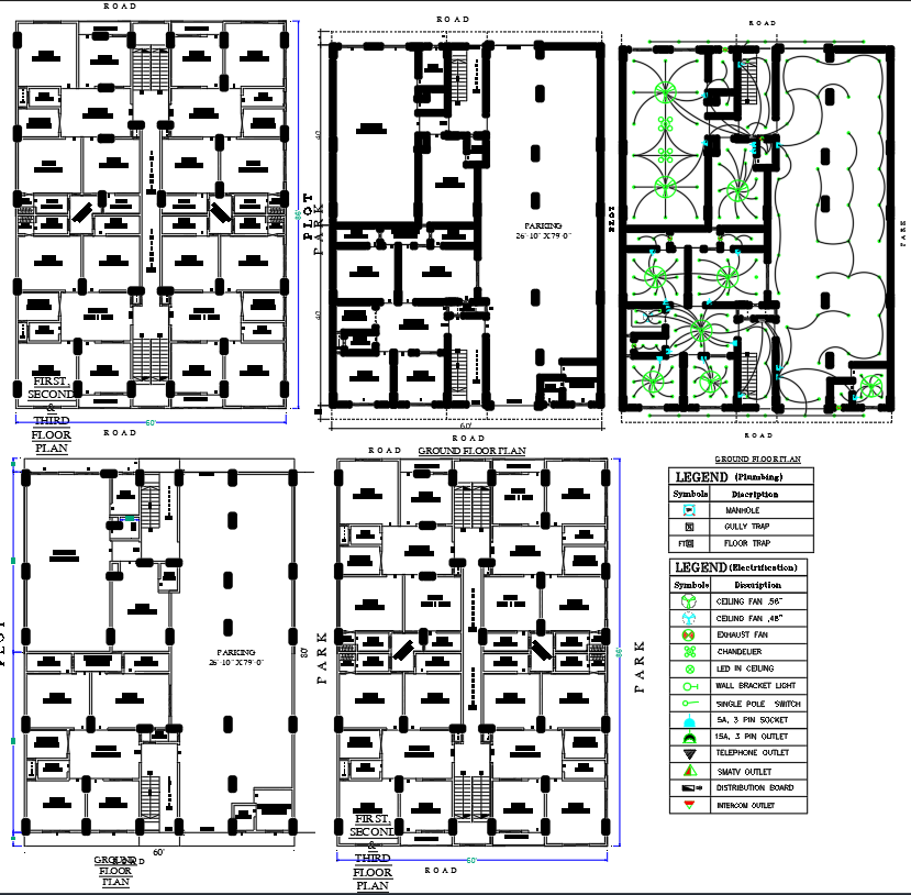
This architectural CAD drawing provides a complete multi-floor electrical wiring layout along with detailed floor plans for a residential building. The plan includes ground floor, first, second, and third floor arrangements, each displaying electrical symbols for ceiling fans, chandeliers, wall bracket lights, tube lights, 5A and 15A socket points, exhaust fan locations, telephone outlets, TV points, and distribution boards. The ground floor also features a clear parking area sized 26’-10” × 79’-0”, multiple staircases, room divisions, entry points, and pathways. The electrical legend included in the drawing helps identify every fixture and outlet, ensuring clarity during installation. Plumbing symbols such as manhole, gully trap, and floor trap are also shown in the legend for services coordination.
The layout highlights the integration between architectural spaces and electrical distribution, showcasing wiring routes, fixture placements, room positions, and circulation flow around the central corridors. The landscape section includes plantation arrangements and pathways, enhancing environmental design coordination. Each floor plan reflects accurate column positions, wall thickness, door swings, and service zones, making the drawing ideal for electrical engineers, architects, and interior designers working on residential building layout planning. With its detailed symbol guide and multi-level clarity, this CAD plan supports safe, accurate, and efficient electrical system implementation.
File Type:
DWG
File Size:
3.9 MB
Category::
Electrical
Sub Category::
Architecture Electrical Plans
type:
Gold
Uploaded by:
K.H.J
Jani
